Module Structure

Contents
The structure of PLE is of a modular nature with basic modules to perform basic flexibility and stress/strain analysis and special modules to accommodate special applications. Various "Code checking" modules are available to directly adhere to specific code requirements. Hence, PLE user can tailor the (functionality of the) program to fit their actually need, reducing costs and complexity in the process.
However, the main model is kept as free from code based ad hoc requirements as possible.
As a result, with the ongoing development of PLE in the wake of new Pipeline Codes becoming available and new construction and installation methods developed, new modules are added in time to include further advanced functionality. Especially the fit-for-purpose analysis on existing pipelines is a first order technical challenge.
The module structure
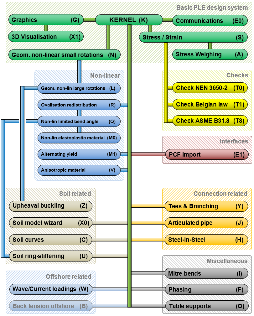
PLE is composed from a series of modules, each module performing a special aspect of pipeline behaviour. The modules are optional, except for the kernel module (K). This module is required to calculate the overall pipeline behaviour with the pipeline being a single, continuous line. The minimum configuration available for purchase or rental is the 'Basic PLE Design System' which includes all the modules highlighted in green in the image below (modules KSAGNE0X1).
The general stress/strain check is contained in the stress strain module (S), but additional check regimes are available and contained in the 'Belgian Law' (T1), 'NEN 3650-2' (T0) and 'ASME B31.8' (T8) modules. In the picture below, these modules are yellow.
To add particular modules sometimes other modules are required as well:
•To apply the material non-linear module (M0), the geometrical non-linearity module (N) contained in the 'Basic system', the ovalisation redistribution module (R) and the non-linear limited bend angle module (Q) are required (blue). But the geometrical non-linearity module (N) can be used separately.
•The ovalisation redistribution module (R) requires the stress/strain module (S).
•The non-linear limited bend angle module (Q) requires the ovalisation redistribution module (R).
•The upheaval buckling module (Z) can be used without additional modules but then the rotations are limited to .3 radian. In most cases the actual rotations will be higher and thus the geometric non-linear large rotations module (L) is required as well.
•For the mitre bends module (I) the non-linear limited bend angle module (Q) is required and thus also the ovalisation redistribution module (R). These requirements only apply when the analysis type is 'General'. For all other types no extra modules are needed.
All other modules can be used without the use of additional modules.
The general modules
|
Name |
Description |
Kernel |
The core of the program, including project generation, loading, and saving; data entry and verification; display of input data and results in table form; printing and more. Only very limited calculation possibilities (linear calculations only, no stresses calculated). This module is required. |
|
Graphics |
Allows graphic representations of data in X-Y or polar plots; drawing of the pipe and copying or printing of graphs. Single curves can be shown as well as multiple curves and curves from different projects. |
|
Visualisation |
Shows a 3D representation of the configuration. The visualisation can be rotated and zoomed. Result values can be visualised on the pipeline as coloured elements. Blue elements having the lower values via green to red elements with the highest value. |
|
Communications |
Allows to import input table data or to export input or output table data. Importing and exporting take place with Microsoft© Excel-files. With graphical representation of results of calculations (see the Graphic module), a facility is available to copy the drawing/graph to the Windows clipboard or to export it to a file, either in vector format (as Windows Metafile Format (*.wmf) file) or in PNG format (as Portable Network Graphics (*.png) file). |
|
PCF Import |
Allows to import pipeline configurations through the Isogen PCF file (*.pcf). This Piping Component File can be generated by a variety of pipeline and piping design programs such as AutoCAD Plant3D, Intergraph Smart 3D, PDS, CADWorx etc.
|
|
Phasing |
Allows the initialisation of the pipe/soil structure by means of import of a displacement/reaction vector from another design database on the condition that the number of pipe elements is equal. There are three initialisation options: •"Continue", introducing pipe deformations together with elastic soil deformations •"Phasing", introducing pipe deformations together with elastic + plastic soil deformations •"Pre-Displacement", introducing fixed deformations for the pipeline The method of calculation of internal forces and reactions in the receiving pipeline structure is the same as specified in the providing pipeline structure (linear or non-linear geometric analysis). |
The calculation modules
|
Name |
Description |
Stress |
Allows detailed stress calculation in selected pipe cross-sections. Stresses are calculated in 48 equidistant points over the circumference at the inner and outer wall side. |
|
Stress Weighing |
Allows calculation of Mohr, Tresca, Von Mises and uniaxial stresses from the calculated stress components taking into account weighing factors for each type of stress component (primary and secondary stresses). |
|
Ovalisation Redistribution |
In the stress module local stressing of the pipe cross-section is calculated on basis of the "ring" stiffness, loaded by the local soil reactions. This module provides a facility to redistribute local soil reactions according to the local ring stiffnesses and soil reaction loading/supporting angles. As such the redistribution of stresses due to the interrelation of consecutive rings is "translated" into a redistribution of soil loads. If, however, the length of elements chosen is larger than the redistribution characteristic wave length at that location the redistribution influence will be negligible. |
|
Geometric Non-Linear (small angle) |
Both the small angle- and large angle-module allow to calculate the displacements and internal forces and related soil and supports reactions, based on equilibrium of the external load system on the deformed pipe structure. Both modules allow elastic bends to be specified. This module limits rotations to 0.3 rad. |
|
Geometric Non-Linear (large angle) |
Similar to the small angle-module. However, rotations larger than 0.3 rad are allowed. |
|
Non-Linear Limited Bend Angle |
In the kernel module the common, standard bend stiffness and stress intensification procedure is applied. This procedure is based on an "infinite" bend angle approach, meaning the bend is not stiffened by the adjoining straight pipe legs. With this module, the limited bend angle is taken into account, based on an extensive pipe bending test program performed by TNO. The stiffening from the adjoining pipe legs in general causes the bend stressing to be less than based on the standard method. In the standard method, the bend stiffness is independent of the bending curvature of the bend section. In reality the ovalisation of the cross-section causes the stiffness factor to be non-linear with the curvature. This is taken into account. As a result of the ovalisation in the bend the adjoining straight pipe legs will become ovalised as well, resulting in an ovalisation distribution over the legs and bend in between. This redistribution of the ovalisation and inherent stressing is taken into account. The interaction between soil loads at bends and the resulting cross-sectional ovalisation and related longitudinal pipe bending is taken into account. As a result the much stronger bend cross-section for lateral soil loading is included.
|
|
Non-Linear / Elasto-Plastic Material |
Due to yielding of the pipe material, the relationship between stress and strain becomes non-linear and results in permanent strains. The pipe cross-sectional yielding and the circumferential wall yielding are taken into account and verified based on results from a test program. The stress/strain relationship may be based on a bilinear stress/strain diagram, but also on various built-in diagrams to account for micro-yielding at stresses lower than the specified yield stress. Stress stiffening is an option as well. Limits to the straining are also based on local buckling limits and on excessive yielding strains.
|
|
Alternating Yield |
This module introduces functionality for calculating alternating yield load case in pipelines. This feature enables users to assess the pipeline's behaviour under cyclic loading conditions by comparing stresses from two different pipeline load cases. |
|
Anisotropic Material Behaviour |
This module enables to distinguish between the material stiffness modulus (E0) in longitudinal and circumferential direction and to distinguish between normal and bending stressing. The Poisson's ratio may be differentiated from axial to circumferential stressing and vice versa. As a result sandwich wall composites can be simulated as well. |
|
Soil Curve Extension |
This module adds additional functionality to design function 3.2 and enables the use of a spatial "slack" space around the initial position of the pipeline. Once the displacement of the pipeline becomes larger than the specified slack in that direction the soil will provide a soil reaction. The slack is specified as a 3D space around the pipeline (1 axis in vertical direction, with separate specification upward and downward, 1 axis in horizontal direction and 1 axis in longitudinal direction) shaped as an unsymmetrical ellipsoid. As long as the pipeline moves in the lateral slack space, the friction is not activated. The slack space may vary along the pipeline axis. Furthermore, this module provides the facility to shape the displacement/soil reaction curve as a TGH function with the derivative at the displacement = 0 equal to the specified k-value in that direction and an asymptotic axis equal to the specified ultimate soil reaction in that direction. |
|
Soil Ring-Stiffening |
The stiffness of the soil counteracting the ovalisation of a cross-section is taken into account both in the 'beam' calculation and the 'ring' calculation resulting in lower ovalisations and stresses, especially of importance for pressureless flexible and/or thin walled pipes. Horizontal soil support springs are applied at the points of the cross-section that move outward. To the soil springs the value of the horizontal or vertical bedding constant without uncertainty factors is assigned whichever is the smallest one. The soil resistance is maximised at 50% of the smallest bearing capacity in accordance with the Dutch code NEN 3650-2. In case of pressureless thin walled steel pipe or pressureless plastic pipe the resulting ovalisation may be reduced by factors.
|
|
Tees & Branching |
This module allows to specify tees and branches to the main pipeline. Tees to tees are allowed as well. Tees may be looped. The tees module includes a T-piece specification option including bending stiffness and stress intensification determination. |
|
Steel-in-Steel Pipeline |
Using this module pipelines with a very high temperature can be calculated (e.g. 130 °C for district heating pipelines). The medium tube is preheated and then fixed to the casing tube. Afterward's the medium tube is cooled down causing a tensile force in the medium tube and an equal pressure force in the casing tube. This process is called thermal prestressing. In the operating phase resulting stresses will be lower than without prestressing. To perform these kinds of calculations also the phasing module (F) is necessary.
|
|
Articulated Pipeline |
With this module one or a series of construction joints can be modelled. Several (9) joint types are available, for instance hinges and socket-spigot connections with user defined (maximum) degrees of freedom. The rate of free axial movement in the socket can be specified both in case of compression and in case of tension. Moreover, the possible free rotation may be set to a maximum value. Furthermore, this module allows to model joints with axial, lateral and torsional stiffnesses, to be specified by the user. With this option, the program reports whether the socket connection will leak or not in case of a joint that is not tension resistant. |
|
Mitre Bend |
This module enables the user to configure mitre bends. Where a smooth bend consists of curved elements, a mitred bend is built up of straight parts with a kink in the middle. When the Analysis type is set to 'General' parameters are calculated according to the TGSL-1986. For the other analysis types the parameters are calculated according to NEN 3650-1:2020. The TGSL method has proven to give more accurate results than the NEN method.
|
|
Table Support with Friction |
This module enables the usage of a special non-linear support in the sense that the support is active only in vertical downward direction and the resulting support reaction may generate a horizontal friction reaction force if the pipeline tends to move over the table support. In case of an upward movement of the pipe, the support is not active. If no supporting angle has been specified, the support reaction force acting on the pipeline is introduced as a shear force based on the assumption of a local stiffening of the pipe cross-section and as a result no wall bending stresses are introduced. |
|
Back tension offshore pipe-laying |
Under development |
|
Wave / Current Loadings |
This module is specifically applicable for offshore pipelines and riser tie-in structures. The loading determination is based on Morison’s formula with Cd, Cm and Cl factors to be specified. The current profile is supplied as a higher order function of the water depth. The influence of the wave shape on the current profile is accounted for. The wave is specified by its height and period, crest location and wave direction. The wave may be long- or short crested. Wave shape may be specified as Airy or 5th order Stokes. The short crested wave is based on Airy. Wave slamming in the splash zone is taken into account. The dynamic influence of the wave frequency or vortex shedding can be taken into account as well as nearby large diameter structural elements that influence the local water velocity. An adapted outer diameter due to external coatings and eventually weight coating and related adapted mass can be accounted for. A series of wave types and current profiles can be specified, however, only one combination of wave and current can be activated at any time. Apart from the generated wave/current forces, various determined wave, current and loading properties are shown in the output tables. |
|
Upheaval Buckling |
In this module the soil mechanical parameters are adapted after each iteration to meet the values valid at the newly calculated depth location. This option is useful for so-called upheaval buckling calculations where the pipeline may move to the ground level due to high axial forces caused by high temperatures.
|
|
NEN 3650-2 Rules Check |
Using this module, a separate stress calculation facility as a parallel option to the general stress module is available to calculate the stress components Sp and Sv according to the Dutch NEN 3650-2:2020+A1:2024 Rules for Pipelines. The stresses are expressed as unit-stresses to the specified limit stress of the pipe material. A stress classification facility is provided, showing as well the cross-sections in which yielding of the pipe material occurs. The stress-weighing module is required for this module, but stress weighing factors are predefined implicitly. Load and/or partial factors for the neutral/real top soil load (SOILNB) and the optional top load (TOPLOAD) have to be specified explicitly. The check stress Sv:pm relates to a primary membrane stress due to primary loads (force-induced loads) and the check stress Sv relates to primary + secondary stresses (wall bending stresses) due to primary + secondary loads (displacement-induced loads). |
|
Belgian Law Rules Check |
In Belgium the limit states of a pipeline are set by law and in case of gas pipelines specific details are referred to the ASME-B31.8 Pipeline Code. The check criteria and performance of the checking are contained in this module. Additional checks, e.g. on minimum wall thickness, are performed as well. The manufacturing tolerance on the wall thickness can be specified as well in absolute wall thickness reduction. |
|
ASME B31.8 Rules Check |
With this module, checking on the criteria as contained in the ASME B31.8 Pipeline Code is possible. The specific stress checking enabled by this module is based on the various criteria set for combinations of stresses. |
|
Soil Model Wizard |
The Soil Model Wizard is an add-on module for PLE that simplifies the obtainment of soil mechanical values through basic soil properties. |
Modules (last modified: May 7, 2026)