Alternating Yield Load Case

Contents
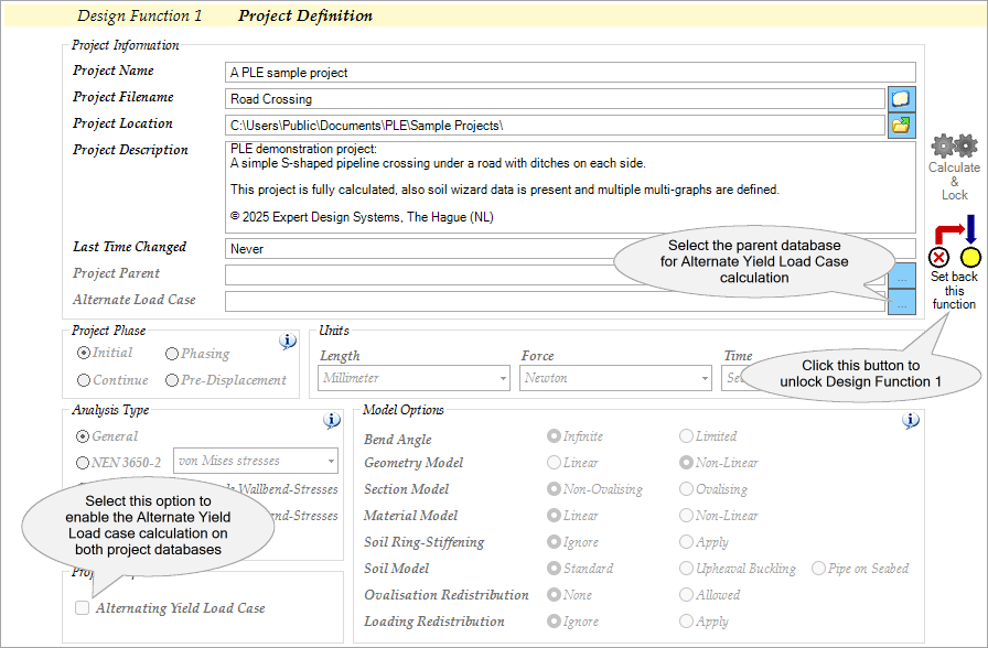
Initiate pipeline design
Alternating Yield Load Case
This option enables the advanced functionality for analysing the behaviour of pipelines under cyclic loading conditions, specifically focusing on the phenomenon of alternating yield.
Alternating yield is a term used in materials science and engineering to describe a phenomenon where a material undergoes reversible plastic deformation under cyclic loading. When a material is subjected to alternating loads, it can experience cyclic deformation without undergoing failure. However, if the stress exceeds a certain threshold, known as the yield strength, the material undergoes permanent deformation or yielding. This process of deformation is known as alternating yield.
In PLE, this is done by comparing stresses from two different pipeline load cases. These load cases represent different operational scenarios, such as varying fluid pressures, temperatures, or external loads, which the pipeline may experience during its service life. Hence, two PLE project databases are required to perform this calculation, each containing distinct load cases.
![]() This option must be enabled in both PLE project databases. A warning will be given if this is not the case.
This option must be enabled in both PLE project databases. A warning will be given if this is not the case.
The initial project database, referred to as the parent database, encompasses the first load case, while the subsequent project database, known as the child database, houses the second load case.The determination of the alternating yield load case will be conducted within the child database. Hence, the results of this calculation will be stored in the child database and presented through two output tables found in Design Function 6.2, namely ASTRMAX and ASTRESS.
As PLE compares stresses from two load cases, it's crucial that both project databases contain identical pipe sections as specified in the SECTION table. This table indicates the pipeline segments where stress calculations must be performed.
![]() Stress calculations must be completed in the parent database before linking it to the child database.
Stress calculations must be completed in the parent database before linking it to the child database.
![]() Both PLE project databases must be created using the same PLE version and contain the same pipeline configuration resulted in the same number of nodes and pipe element division. A warning will be given if this is not the case.
Both PLE project databases must be created using the same PLE version and contain the same pipeline configuration resulted in the same number of nodes and pipe element division. A warning will be given if this is not the case.
The assessment method used is based on the method described in the Dutch standard NEN 3650-2:2020+A1:2024. In this method, stresses are compared for the pipeline under two different load combinations. Both combinations should represent the extremes of the loads on the pipeline. Often (but not necessarily always), these will be the BC3 and BC4 load combinations as described in the NEN 3650-2:2020+A1:2024; BC3 is the load combination where the internal pressure is zero, while BC4 is the load combination with internal pressure and (maximum) temperature differences. In this method, the differences in the two principal stresses σ1 and σ2 are calculated using the Mohr circle formula:
with the third principal stress σ3 assumed to be zero. This calculation takes place over the entire circumference of the element and takes into account that the direction of the stresses at that circumference point may be different. Ultimately, the maximum of the differences |∆σ1 - ∆σ2|, |∆σ2 - ∆σ3|, and |∆σ3 - ∆σ1| is decisive. The difference must be smaller than the limit value (Re + Re(θ)) / γm. |
This alternating yield load case assessment is available for the following combination of Analysis Type and Model Options in PLE: |
Since this assessment is about comparing stresses from two different pipeline load cases then it is obvious to have two PLE project databases to be compared. 1.Open the first PLE project oMake sure that the project property Alternating Yield Load Case in Design Function 1 is selected oProcess this project to perform the calculation up to and including Design Function 6.2 oSave this project oThis project will be used as the parent database 2.Open the second PLE project oThis project is the child database and need to be linked to the parent database oGo to Design Function 1, select the first PLE project above as Alternate Load Case database in the Project Information group oMake sure that the project property Alternating Yield Load Case is selected as well oMake sure that the selected Analysis Type is exactly the same as the first project oProcess this project to perform the calculation up to and including Design Function 6.2 oThe assessment results can be found the output table ASTRMAX and additional output table ASTRESS found in Design Function 6.2
|
![]() This option requires module M1.
This option requires module M1.
![]() This option is not available in the free Educational version.
This option is not available in the free Educational version.
H1003W (last modified: Feb 10, 2026)
See also: