Pipeline Joints (Articulated Pipelines)

Contents
Internal boundary conditions
If the pipeline cannot be considered as a continuous beam, as in case of articulated pipelines, the connection type between the separate pipe sections has to be specified.
Examples of articulated pipelines are (nodular) cast iron, (reinforced) concrete, plastic (PE, PVC) and glazed stoneware pipelines provided with whether or not anchored socket-spigot connections.
Other applications are articulation joints at the transition to rigid (building) structures and expansion joints or compensators in hot pipelines.
A pipe joint is a mechanical assembly used to connect two pieces of pipe. The primary purpose of a pipe joint is to ensure a secure, leak-free connection, allowing fluids or gases to flow through the piping system.
Pipe joints are essential in any piping system because the length of pipes is limited. To create a continuous piping network, pipe joints are used. They also provide flexibility and can accommodate mechanical stresses such as thermal expansion, contraction, and vibrations.
There are several types of pipe joints, each with its own applications and advantages:
When joining two pipes or components with a spigot and socket joint, the spigot of one component is inserted into the socket of the other component. The fit is typically snug to ensure a watertight or airtight seal, depending on the application.
oSpigot: The spigot refers to the male component of the joint. It is a cylindrical projection or rod that fits into a corresponding socket or hole.
oSocket: The socket is the female component of the joint. It is a hollow, cylindrical opening or receptacle designed to receive the spigot.
These joints are often used because they provide a secure connection that can withstand pressure and prevent leakage. Additionally, they are relatively easy to assemble and disassemble, making maintenance and repairs more straightforward. The presence of a stopper on either the spigot or socket can further enhance the stability of the joint by preventing over-insertion and ensuring proper alignment.
 |
 |
Non-tensile resistant type |
Tensile resistant type |
In a sleeve joint, a sleeve refers to a cylindrical component that fits over the ends of two pipes or tubes to join them together. The sleeve typically has an inner diameter slightly larger than the outer diameter of the pipes it connects.
Sleeve joints provide a simple and cost-effective way to connect pipes or tubes of the same or similar diameters. They are often used for temporary or low-pressure applications where welding or soldering is not necessary or practical. However, they may not be suitable for high-pressure or critical applications where a more secure or permanent connection is required. Additionally, the effectiveness of a sleeve joint can depend on factors such as the quality of the sleeve and the tightness of the fit between the sleeve and the pipes.

A ball joint consists of a spherical bearing enclosed in a socket. This setup allows for a wide range of motion in multiple directions, including rotation and tilting.
 |
 |
Butt welding end ball joint |
Flanged end ball joint |
A hinge joint allows for rotation around a fixed axis in one direction. It typically consists of two parts, one with a cylindrical projection (the hinge pin) and the other with a corresponding hole or slot.
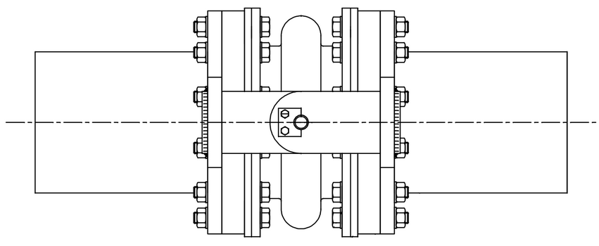
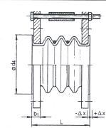
Bellows-type connections are used in applications where there is a need for flexibility and movement between two components while maintaining a sealed or protected environment. They are often used to compensate for thermal expansion, vibration, or misalignment between pipes. They allow for movement and flexibility while preventing leakage or damage to the pipes.
 |
 |
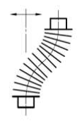 |
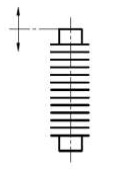
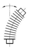
Axial movement |
Angular movement |
Lateral movement |
The bellows type of connection can be specified with stiffnesses in axial, transverse, torsional and rotational direction.
Examples:
 |
 |
Expansion joint |
Compensator |
Articulation joints
Articulation joints are mechanical components that allow for movement or rotation between two connected parts while maintaining structural integrity. These joints are crucial for enabling movement and flexibility in various mechanical systems while maintaining stability and control. They come in different designs and configurations to suit specific applications and requirements.
An articulation joint can consist of other types of joints, depending on the specific design and application. For example:
•Socket-spigot connection: the connected components can rotate or pivot relative to each other while maintaining structural integrity.
 |
 |
Non-tensile resistant articulation joint |
Tensile resistant articulation joint |
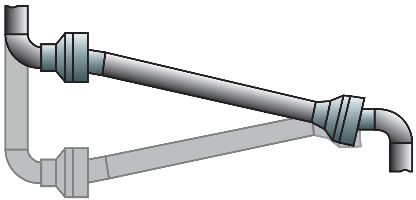
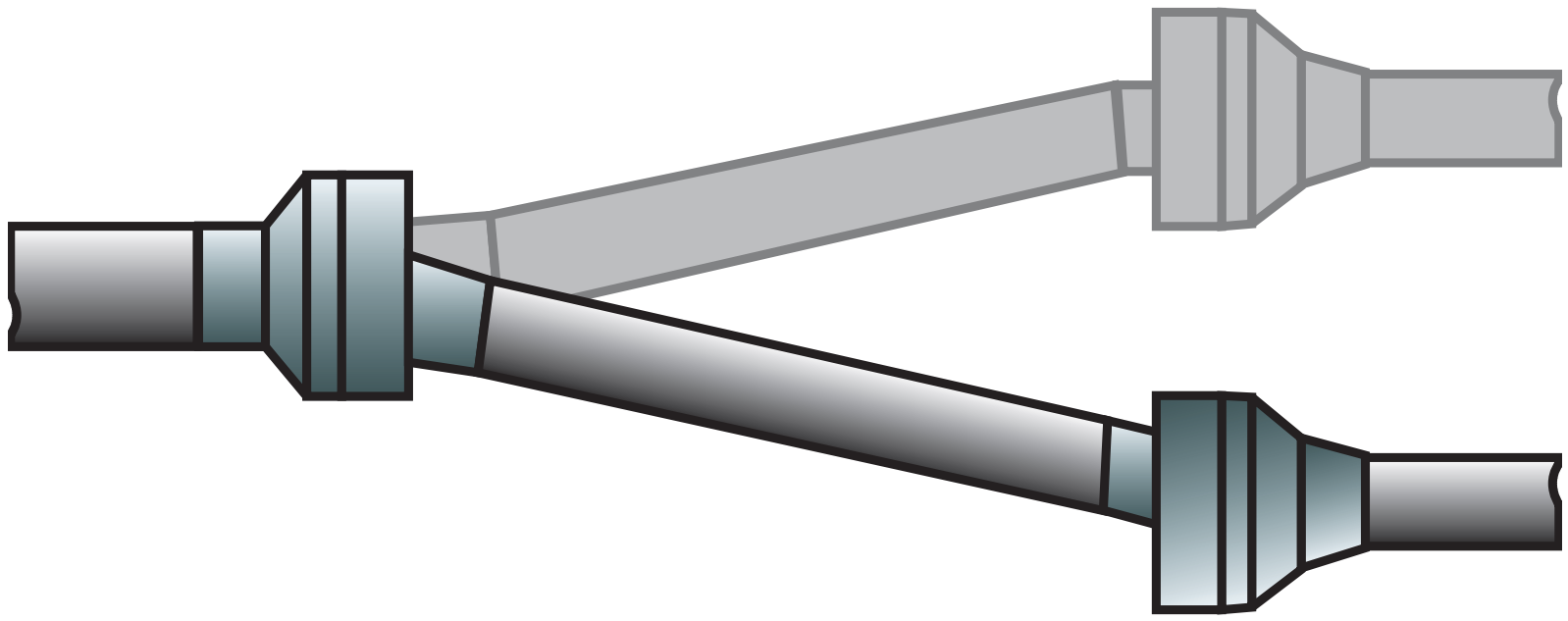
•Ball joint: this connection allows for a wide range of motion in multiple directions, including rotation and tilting.
 |
 |
 |
Linear expansion/contraction |
Pipe alignment |
Pivoting/rotation movement |
•Hinge joint: this connection enables rotation around a fixed axis in one direction.

Direction of local X-axes for different types of joints
With Socket types the local X-axis is equal to the local X-axis of the adjacent element with the lower element number.
With Spigot types the local X-axis is equal to the local X-axis of the adjacent element with the higher element number.
For all other types (“Sleeve”, “Ball”, “Hinge”, “Tight” and “Bellows”) the local X-axis is perpendicular
to the bisector of the local X-axes of both adjacent elements.

Limitation of the maximum rotation
The resulting maximum rotation MaxRot (α in the figure) in output table J-SDATA may become less than the value of AllowRot assigned in input table JOINTS, due to the pipe diameter and the specified clearances (x-C and x-T).
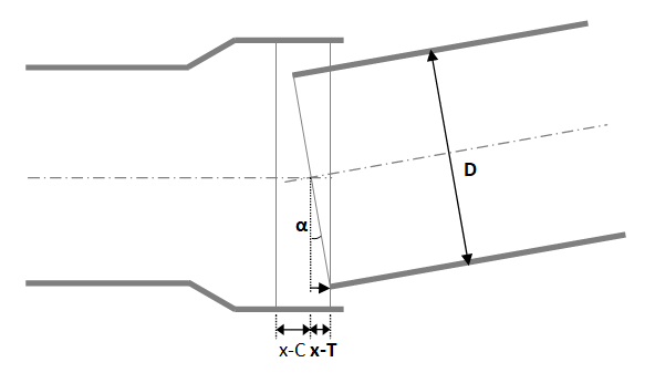
The maximum rotation can be calculated as ½ D sin(α) ≤ x-T (and ≤ x-C).
When e.g.
AllowRot |
= |
5.0 |
° |
(given by the pipe manufacturer and assigned in table JOINTS) |
|
D |
= |
508 |
mm |
||
x-T |
= |
20 |
mm |
Then
α |
= |
|
MaxRot |
= |
4.5 |
° |
(calculated by PLE and reported in table J-SDATA) |
![]() In case the joint is a 'stop' type, and the rotation reaches the calculated MaxRot of table J-SDATA, table DISPJNT of design function 5 will report 'STOP' in column EFFECT. Column dPHI-yz will report the 4.5°.
In case the joint is a 'stop' type, and the rotation reaches the calculated MaxRot of table J-SDATA, table DISPJNT of design function 5 will report 'STOP' in column EFFECT. Column dPHI-yz will report the 4.5°.
![]() In case the joint is a 'leak' type, and the rotation exceeds the calculated MaxRot of table J-SDATA, table DISPJNT of design function 5 will report 'LEAK' in column EFFECT. Column dPHI-yz will report the actual rotation.
In case the joint is a 'leak' type, and the rotation exceeds the calculated MaxRot of table J-SDATA, table DISPJNT of design function 5 will report 'LEAK' in column EFFECT. Column dPHI-yz will report the actual rotation.
InternalBoundary (last modified: Oct 20, 2025)
See also: